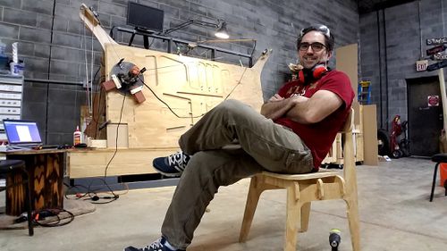
Maslow CNC
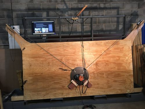
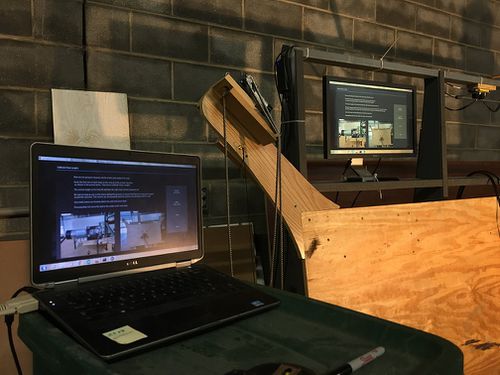
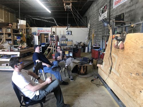
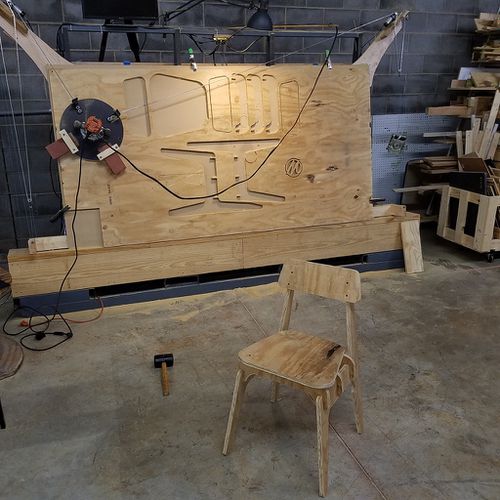
Matthew, Tanju, Mike, Alex, and Chuck have been setting up and tweaking this DIY CNC to cut full sheets of plywood!
The Maslow CNC requires advance training and should not be used with consulting first with the members listed above.
General Info: http://www.maslowcnc.com/
Rough Notes & Lessons Learned
- Disable "Sleep" power option on the computer running Ground Control. CNC cutting at a large scale is time consuming, having the computer go to sleep in the middle of a job will result in need to abort the job and recalibrate
- Always verify Z-axis zero and smooth z-travel of the router before beginning to ensure the target depth can be achieved
- When adding Tabs, they must meet minimum size requirements or will not be visible in application. For tabs, they need to be bigger than two bit-diameters. We've been using 1/4" bit. Twice that is 1/2". If you ask MakerCam for a 1/2" tab it will be invisible due to the bit size and so I added an extra 1/8" to get to 5/8" (0.625"). Figured that out after approximately more than one pain frustrating hour of not getting any tabs
- Preview your Exported MakerCam.com GCode by uploading to ncviewer.com
Learning to Cut with the MaslowCNC:
Following the below procedures assumes you have already attended a Maslow CNC or other CNC Meetup at The Maker Station and were given a hands on overview. Below is only for future reference:
- Navigate to MakerCam.com
a. Zoom Out to find intersection of X and Y (HOME) b. Open a simple SVG file or Insert a Shape. Keep object relative to HOME. c. Select area, click CAM, Profile Operation i. tool diameter (in) 0.25 ii. target depth (in) -0.8 iii. inside/outside: Outside iv. safety height (in) 0.5 v. stock surface (in) 0 vi. step down (in) 0.05 vii. feed rate (in/minute) 60 viii. plunge rate (in/minute) 30 ix. direction: Counter Clockwise x. Click OK d. Click CAM, click calculate selected e. Select area, click CAM, add tabs to selected i. tab spacing (in) 5 ii. tab width (in) 0.25 iii. tab height (in) 0.25 iv. Click OK v. Blue circles indicating tabs can be dragged or deleted f. Click CAM, click Export Gcode, click All, click Export Selected Toolpaths i. Save to Laptop with unique filename.
- Navigate to NCViewer.com, click Upload, select file just created
a. preview paths and understand motions that will occur b. If acceptable, minimize window to reference later. c. Know you can jump directly to any line of gcode shown here.
- Verify Power on Laptop, Arduino, and Shield, and Laptop set to High Performance
- Verify no metal clamps or metal screws on cutting surface
- Physically push router in towards cutting surface so bit touches cutting surface
- On Laptop, open Ground Control software on desktop
- Click Z-AXIS, raise or lower for Bit to touch cutting surface, click Set Zero, click Done
- Click HOME. The Z-Axis will automatically raise the bit and the sled will move to X Y Zero
- Click ACTIONS, click Open, select File
- Notice file will open relative to where it was positioned in MakerCam.com
a. If you need to cut piece in different area, click the directional arrows to move sled. b. click “Define Home” which is a temporary home for this session only. c. Note the part moves relative to “Define home” d. Click the PLAY button to start processing the gcode and start cutting. e. Note the PAUSE button only pauses the next line of code f. For immediate needs, you can click STOP
