Difference between revisions of "Barbie Maker Vette - Glitch Candy Kart"
(→Electrical) |
(→Electrical) |
||
| Line 91: | Line 91: | ||
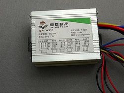
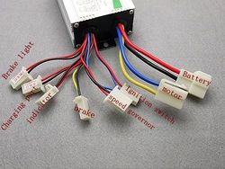
* USA Motor Speed Controller Electric Bike Scooter 24V 500W | * USA Motor Speed Controller Electric Bike Scooter 24V 500W | ||
** Shipped direct from China, it came with this awesome wiring diagram and instructions | ** Shipped direct from China, it came with this awesome wiring diagram and instructions | ||
| − | ** [[File: | + | ** [[File:Controller1.JPG|250px]] [[File:Controller2.JPG|250px]] |
Revision as of 17:34, 10 May 2015
Contents
reference: http://disney.wikia.com/wiki/Candy_Kart
General Info
Planning for wholesale improvement this year building off of the failures from our inaugural 2014 build.
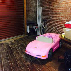
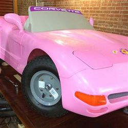
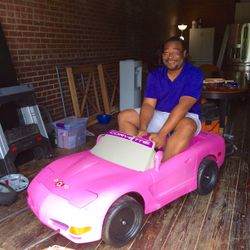
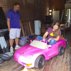
We scored this sweet Baribe Corvette off of craigslist and now aiming for Glitch's Candy Kart from Wreck It Ralph moxie theme.
Specs:
- Motor: 36VDC 500W brushed
- Controller: 24V 500W
- Drivetrain: Gear Ratio= 80:9 swapable to 5.9; with #25 Chain, Dead Axle, Single Wheel Drive
- Wheels: TBD
- Batteries 12V 36Ah
- Moxification: TBD Glitch
- Top Speed: TBD
Build Notes
Frame and Chassis
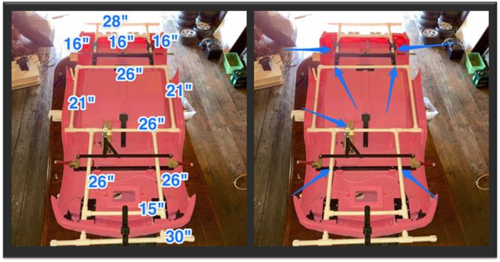
Frame mockup
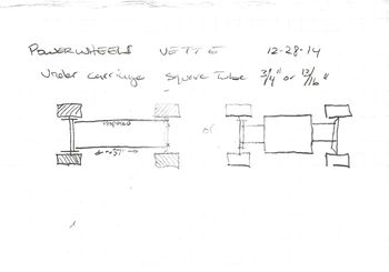
This powerwheels seemed to be an older vintage as the frame's cross members and steering assembly are made of 3/4" steel tubing. Finding this was a pleasant surprise. We decided to keep the existing frame and steering geometry intact and simply build off of it.
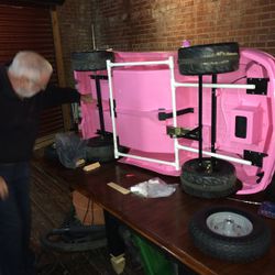
We discovered that the front and rear cross members are not on the same plane (different elevations) due to the steering linkage and we couldn't figure out how to measure their positions as they are bolted to the car's plastic frame. Instead we bought about $5 worth of half inch PVC to mock up a frame and build around the body attempting to minimize any cutting into it. This allowed us to better visualize what we needed and plan for cuts, weld preps, etc.
Frame fabrication
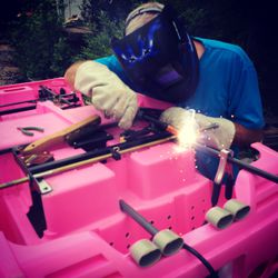
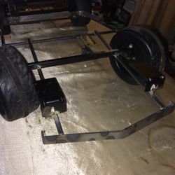
We elected to go with 1/2" square tubing on the frame, because weight. Some of us tried some back of the envelope beam stress calculations to size the tubing and figured that 1/2" tube wouldn't cut it. But in the end decided to go with it and just repair and reinforce if anything breaks or yields.
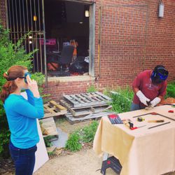
Several people got a chance to develop welding skills on this. A few kids got a chance to observe as well.
We used a cheapo FCAW 110 V Welding Machine from Harbor Freight that seemed to be good enough for this job.
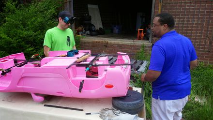
We tacked welded up the frame on the car body itself and then removed the body to finish the job.
The car's body definitely contributes to the stiffness of the assembly. Without it, the frame flexes pretty good about the axle points. Overall with the body secured to the frame, it feels pretty solid. It passed two separate sit tests.
We'll see how it holds up with the batteries and motor and under race loads.
Lastly, in order to comply with the PowerRacingSeries sanctioning body's stringent requirements, a bumper was fabricated. We were pretty happy to have successfully matched the Corvette's front end geometry using similar triangles.
Wheels
The stock axles on the powerwheels are 1/2" while the inner diameter on stock wheels from Northern Tool are 5/8".
Currently not sure what kind of wheels we're going to run. As a test, we printed out some 1/2" x 5/8" sleeve adapter prototypes and if needed, we'll get some turned down out of steel from a local machine shop.
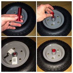
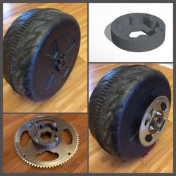
Also, since we're dilly-dallying about making any kind of decision on the wheels, we decided to test out performance using the stock wheels. This being an older vintage powerwheels, the wheels have a rubber traction tread band in the center of the wheel that would be a total shame to just throw away, so we designed and printed a coupling adapter allowing us to mount a sprocket to the stock wheel.
We figure we'll do test runs until either the adapter is destroyed or the wheels are torn up, whichever comes first.
Drive Train
Pictures of the drive train are hard to get. Not very much to say about it either.
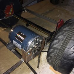
We made a super sophisticated motor mount out of angle iron and left over 1/2" square tubing, and since we haven't decided on wheels yet, we don't know how the sprocket will get mounted yet. We're also holding out for some funding to get a differential scooter transaxle.
For now, we have the following four #25 sprockets and will be experimenting to determine the desired configuration:
- 9T OD 13/16" / 20mm
- 11T OD 1.0" / 25mm
- 80T OD 6-1/2" / 165mm
- 65T OD 5-1/2" / 140mm
We did have a successful motor bump test on the first attempt using Mike's hands as a spark plate.
Don't try this at home.
//[<iframe width="560" height="315" src="https://www.youtube.com/embed/gJv278B5k3M?rel=0" frameborder="0" allowfullscreen></iframe>]
Electrical
Motor Controller:
- USA Motor Speed Controller Electric Bike Scooter 24V 500W
Throttle:
Wiring and Connectors:
- 10 AWG wiring
- SIGA® MC4 Solar Panel Connectors
- Battery Lug Connectors
Batteries:
Battery Charging:
Moxie
BOM
- Motor: 36V 500W brushed DC motor sourced from monsterscooterparts.com clearance section due to a nicked pigtail lead
- Controller: 24V 500W cheapo chinese scooter controller
- Drivetrain: 11T Drive Sprocket + 80T Driven Sprocket;
- Wheels: TBD
